| OCR Text |
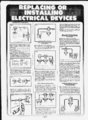
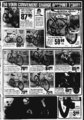
Show THE Fig. SHINGLE-POL- TOGGLE SWITCH E A Fig. Since the first switch is at position (C), current flows directly through terminal (E) to terminal (F). then through handle (G) to turn on the light. Note than when either handle is placed- in the opposite position, the circuit is broken and the light goes out. Note also that if you swing either handle to the opposite position the current flow is made continuous and the light goes on again. E - 1 1 IL i ich re o re biacn at future i ' SWITCHES INSTALLING THREE-WAFOR CONTROL OF OUTLETS BEYOND THE SWITCHES .... f Ine 5 o Poe a. ... i n 4 Sou'f ich Feeds or Breaks ine Current two-wir- SWITCH FOR CONTROL OF ONE OUTLET E The simplest switch system is illustrated in Fig. A. The ordinary single-pol- e toggle switch provides a means for breaking or feeding current to a light, appliance, Shut off all current at main switch box. Mount the two switch boxes at the desired positions beyond the last outlet or light fixture, (Fig. 13). They may be placed as far apart as desired. e feed cable from the last outlet Continue a box to the first switch position. (Fig. I), and a three-wir- e feed cable from the first switch box to the second switch box. etc' The single-poltoggle switch has two brass terminal screws. One wire (usually the black) is cut and connected to the two brass terminals. The other wire (white) is continuous from the power source to the light or fixture. When connecting the wire to the terminal screw of a switch, always turn the loop on the end of the wire in the same direction as the screw threads. If the loop is turned in the opposite direction. B. the tightening of the screw tends to loosen the loop. e Shut off all current at main switch box. A third wire (red. Fig. F). must be added to the power cable for this switch arrangement. The red wire serves as a black wire from the switch to the light or outlet which is to be controlled. Fig. Fig. H F Th'f Switches B I. Aror ml,.!' fen j Way Lui.i rui m D nU'ui i, See CM-- I Tni.'jds If the wire connects to the terminal screw and then runs on. scrape a small section of the wire bare and loop it around the terminal screw as illustrated. C. The use of screw-oconnectors, or solderless will save time and effort when it is necessary to make a splice in any electrical wire. n Fig. c -- . n-.- 0'- Save T.mp in( E" CT'npr'n's vv.-- e j,.;iur't' h th.i! Ciinl'oK Only 0" ior Conlrol ol Oullels Beyond the Continue the black feed wire from the outlet box to the right hand top terminal screw on the right hand three-wa- y switch, (position A. Fig I). Continue the white feed wire from the black wire on the light fixture in the outlet box, (Fig. I). Connect it with the black wire in the three-wir- e feed cable at the first switch box. then continue it on to the right hand top terminal screw, (position B)-- , on the left hand three-waswitch. feed cable Connect the red wire in the three-wir- e to the lower left hand terminal screw on the right hand three-waswitch, (position C), and continue it on through the left hand lower terminal screw. (D). on the left hand three-waswitch. Connect the white wire in the three-wir- e feed cable to the lower right hand terminal screw, (position E), and continue it to the lower right hand terminal screw, (position F). on the left hand three-wa- y switch. When installed in this manner, the light or any series of lights can be turned on from eigher three-wa- y switch position. y Study the diagram in Fig. F carefully. You will note the white wire feed scontinuously from the power source to all fixtures. The black wire is looped on one terminal of the switch while the red wire attaches to the. other. The black wire then runs continuously through to the light or outlet which is not to be controlled while the red wire runs from the switch terminal to connect with the black wire on the controlled light or outlet. With this arrangement, the switch controls the first light or outlet while power continues uninterrupted to the second fixture. HOW A Sop R i" On;if lo' Im Li'ic Sw.t. Oi.'l.'l I An,mr:r,ti-- Oiill.t i'' Swlrhcs y y INSTALLING THREE-WASWITCHES FOR CONTROL OF OUTLETS BETWEEN SWITCHES SWITCH WORKS THREE-WA- The illustration in Fig H uses open knife switches to shoiw how a three-waswitch works. Wire No. 1 feeds directly from the power source to the light fixture. (Fig. 12). However, power just be fed through two wires for the light to function. The flow of power through wire No. 2 is made continuous or broken by the twi switches as illustrated. y Always cover any soldered connection with in- sulating tape If soldered sections are rough an extra layer of tape may be required Insulate an inch or two beyond the soldered connection in each Fin n AM So'r1r"M ( c IS lnfnljt."9 Shut off all power at the main switch box. three-wir- e feed cables to the three-waswitches on either side of the oulet. (Fig 14). A careful study of the diagram will enable you to connect the white, black and red wires without difficulty. The red wire is illustrated as checked in the illustration. Be sine all black, white and red wires are connected exactly as illustrated in the illustration Connect Tape Fig. Insulating Tape At. a q. rr.nl tnf C '' ' "( T0 fo Sor'I'M'S in Or" 5tlCh Bo y po" I Source 0f Power through wire No 2 reaches the first switch center or common terminal (A) If the knife switch handle were at position (B) the current would flow through to terminal (D) but still would not provide a continuous power (low since the knife switch as illustrated is at position G) The light bulb still would not be illuminated at the page 6L Thm Way Srri.nS S'tcrrs or Cor.woi o' Outici Bieen |