| OCR Text |
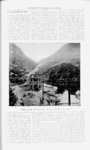
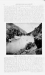
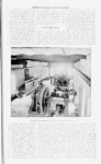
Show 8 MINING REVIEW. INTER-MOUNTAI- N located just below the bridge. This d redwoood, is anpipe, of chored to the bottom by rock piles, and is to be used in the event of its being necessary to drain the reservoirs, without interfering with the lunning of the station. This is accomplished by closvalves, and the staing the head-gat- e tion can thus be supplied from the natural flow of the stream, during such time as the reservoir might be empty. From the valve tower, which is located in the reservoir, there is connected 2S40 feet of steel pipe fifty inches in diameter, the thickness being of an inch, extending through a tunnel 380 feet in length and the thickness of the pipe increasing at the required intervals, reaching at the header one-ha- lf inch, at which point it is sub- steel-bande- one-four- th one rivited joint on the ground. The pipe, as in operation today, is absolutely tight. The generating plant consists of four three-phas- e 450 kilowat sixty-cycl- e General Electric generators, separately set with arexcited, matures parallel to each other, facing up in true line in the building. Each generator is driven directly by one h ay special Pelton wheel, sixty inches in diameter, provided with two nozzles of 3V4 inches diameter.' The nozzles are provided with hood valves for shutting off, so that both good regulation and non-eompound- ed, economical use of water are secured. Each nozzle, at 370 feet effective head, produces 310 mechanical horse power, and drives the wheel 300 revolutions per minute, its economical speed. The The alternators are regulated by an independent lever for each generat r. Each lever is set opposite the switchboard belonging to the machine it controls. It is therefore hand regulati jn throughout. This apparatus, as in tie case of much of the pipe and other fittings, was made by Messrs. Silver brothers of Salt Lake City, from tiie general designs of the engineer. The station switchboard consists of five panels with complete controlling and indicating apparatus, and there is a three-panraising transformer switchboard. The apparatus is protected by ball lightning arresters, and the transformers are cooled by two Sturtevant exhaust fans driven by e two power induction motors. The line conductors consist of twelve el five-hors- Big Cottonwood Power Company. water wheel is keyed directly upon the wires, four circuits of three wires ea hi n bare copper, nd armature shaft, in lieu of a pulley. The all No. 2 us alternators are separately excited. This connected to the same common is accomplished with two 25-W. di- line at the generating and at the rect current exciters, 125 volts; stations. The line loss, in dieach exciter is driven by two stributing 1520 kilowatts at 10,000 v ts, Pelton motors, direct con- is something less than 5 per cent. nected with the armature shaft, The transmission line from gene it- and each set is built upon one .ing to distributing station, is four en cast base plate. Differential gear is miles by pole line. The distribu n used for regulating the exciters. station is owned the Salt Lake nd by This application provides exciting Ogden Gas and Electric ni- i Light two units, n- and at energy in all times one exciter is in reserve. The pany, who rent it to the Big Coi ial exciters are run in multiple, and con- wood Power company at a non u nected to one common bus line on rent. It contains, for step-t- b .ur the switchboard. The three-phas- e gentransformation, nine 160 kilowatt erators are also operated in parallel. blast transformers, from the secon u There are six raising transformers, 265 side of which the Eelectric Light i:n" kilowatts each, of General Electric pany buys the current wholesale by make. meter. This arrangement is a i ,,st RESERVOIR AND DAM jected to pounds pressure per square inch. This pipe was made in sections thirty-tw- o feet long each, with wrought steel flange rivited to each end, with five turns of No. 4 soft copper in each flange for gasket. The flanges were rivited on at the required angles to accomplish a system of long radius curves, there being two horizontal curves, one vertical curve and one compound, taking up vertical and horizontal angles. The shortest curve that was adopted was 294 feet radius, which curves amply provide for expansion joints. There were fifty-on- e angle in this of pipe, flanges the entire length and the shop work, done by Messrs. Fraser & Chalmers, corresponded so closely to the engineering as to accomplish a complete connection with but 165 soft-draw- K. 14-in- ch |